The 20-Second Trick For Volution Bearing
The 20-Second Trick For Volution Bearing
Blog Article
The Basic Principles Of Volution Bearing
Table of ContentsVolution Bearing Things To Know Before You BuyThe 10-Second Trick For Volution BearingThe Ultimate Guide To Volution BearingSome Ideas on Volution Bearing You Should Know
This is the amount of time that a group of apparently similar bearings will certainly finish or exceed prior to the development of a fatigue spall.This calculation can be rather made complex as it depends on the relative sizes of the radial and thrust lots per various other and the get in touch with angle developed by the bearing. It would certainly be too hard to show all the methods of calculating P for all the bearing types shown. For tapered roller bearings, the "K" drive variable is used.
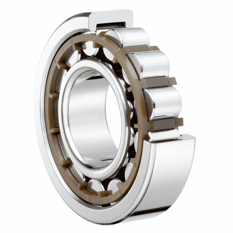
Radial cylindrical roller bearings that have opposing flanges on their inner and external races have a minimal capacity of taking a drive load though the length of the rollers. It is so limited that we do not recommend individuals intentionally do this. Acceptable drive loading is making use of roller ends and flanges for recurring drive and locating purposes.
Several applications do not operate at a constant tons or rate, and to select bearings for a particular rating life in hours based upon the most awful operating problem could confirm wasteful (https://www.merchantcircle.com/blogs/volution-bearing-statham-ga/2024/5/Volution-Bearing-Crafting-Top-Notch-Bearings-for-Extreme-Environments/2716527). Typically, a task cycle can be specified for the numerous operating problems (lots and rate) and the portion of time at each
7 Simple Techniques For Volution Bearing
In such circumstances, a full duty cycle happens within one transformation of the bearing. The two instances could be integrated for numerous anticipated operating problems with reciprocating motion and various height tons and rates. Computing the ranking life when loads and speeds vary entails initial determining the L10 rating life at each running condition of the task cycle.
T1, T2, Tn = percentage of time at different conditions, expressed as a decimal T1 + T2 + Tn = 1 Lp1, Lp2, Lpn = Life in hours for each duration of consistent lots and speed When a bearing does not make a full rotation however oscillates back and forth in operation, a lower equal radial lots can be calculated making use of the formula listed below: Pe = Po x (/ 90)1/e where: Pe = equal dynamic radial tons Po = actual oscillating radial load = angle of oscillation, in levels e = 10/3 (Roller Bearings) 3.0(Ball Brgs) Some applications generate extremely high radial and drive lots, and it may not be literally feasible or feasible to make use of a single bearing that can taking both kinds of load.
When this takes place, the maker designer have to take care to ensure that the radial bearing takes only the radial lots, and the drive bearing takes just the thrust lots. A great way to achieve this is to use a cylindrical roller bearing with one straight race at the "radial" area, as this bearing can not take any thrust.
One method to achieve this is to make the fit of the outer races very loose in their housings: normally.5 mm/.020 In. to 1.0 mm/.040 In. Life adjustment elements enable the original tools maker to far better anticipate the actual solution lives and dependability of bearings that you select and set up in your equipment.
Getting The Volution Bearing To Work
Life change elements, a1, a2 and a3, can theoretically be greater or much less than 1. manufacturer.0, relying on their analysis. In the OEM's process of predicting the solution dependability of his/her tools, it is often necessary to raise the reliability of the chosen bearings to forecast a longer indicate time in between failures
If a lower worth for L10 is calculated with an a1 variable, and it is not appropriate, after that a bearing with higher Dynamic Capacity requires to be selected. Dependability - % Ln a1 element 90 L10 1.00 95 L5 0.64 96L4 0.55 97 L6 0.47 98 L2 0.37 99 L1 0.25 There have been several improvements in bearing design and manufacture over the years that have been confirmed in life tests that result in improved L10 ranking life.
Numerous bearing applications are much from laboratory problems. If the lubrication is remarkable and the running rate high sufficient, a significantly enhanced lube film can establish in between the bearing's inner get in touch with surface areas warranting an a3 aspect better than 1.0.

The Ultimate Guide To Volution Bearing
The following formula is used to determine the System Rating Life: L10sys = (L1-w + L2-w + Ln-w)-1/ w where L10sys = rating life for the system of bearings L1, L2, Ln = rating life for the individual bearings in the system w = 10/9 for sphere bearings and w = 9/8 for roller bearings It has been learned from experience that site bearings call for a minimal employed lots to insure grip for the rolling aspects so they roll as the shaft begins to revolve. https://jasonbrown30666.wixsite.com/my-site-1/post/revolutionize-your-machinery-with-volution-bearings.

Report this page